Send Message
products

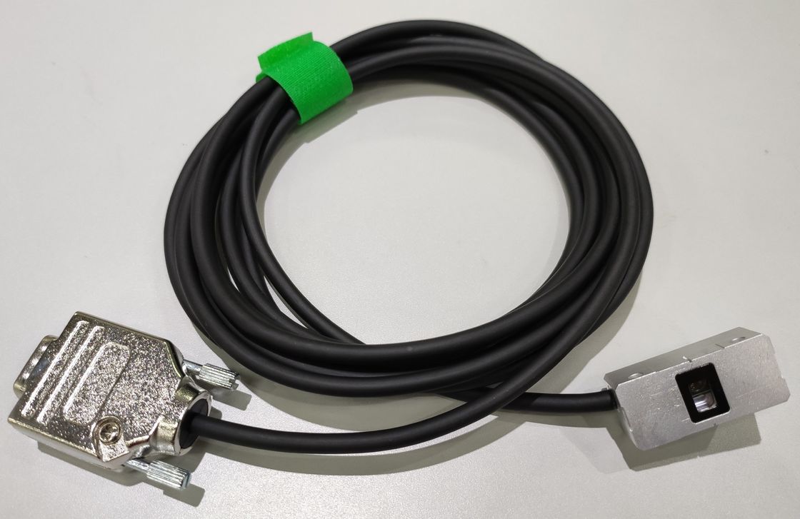
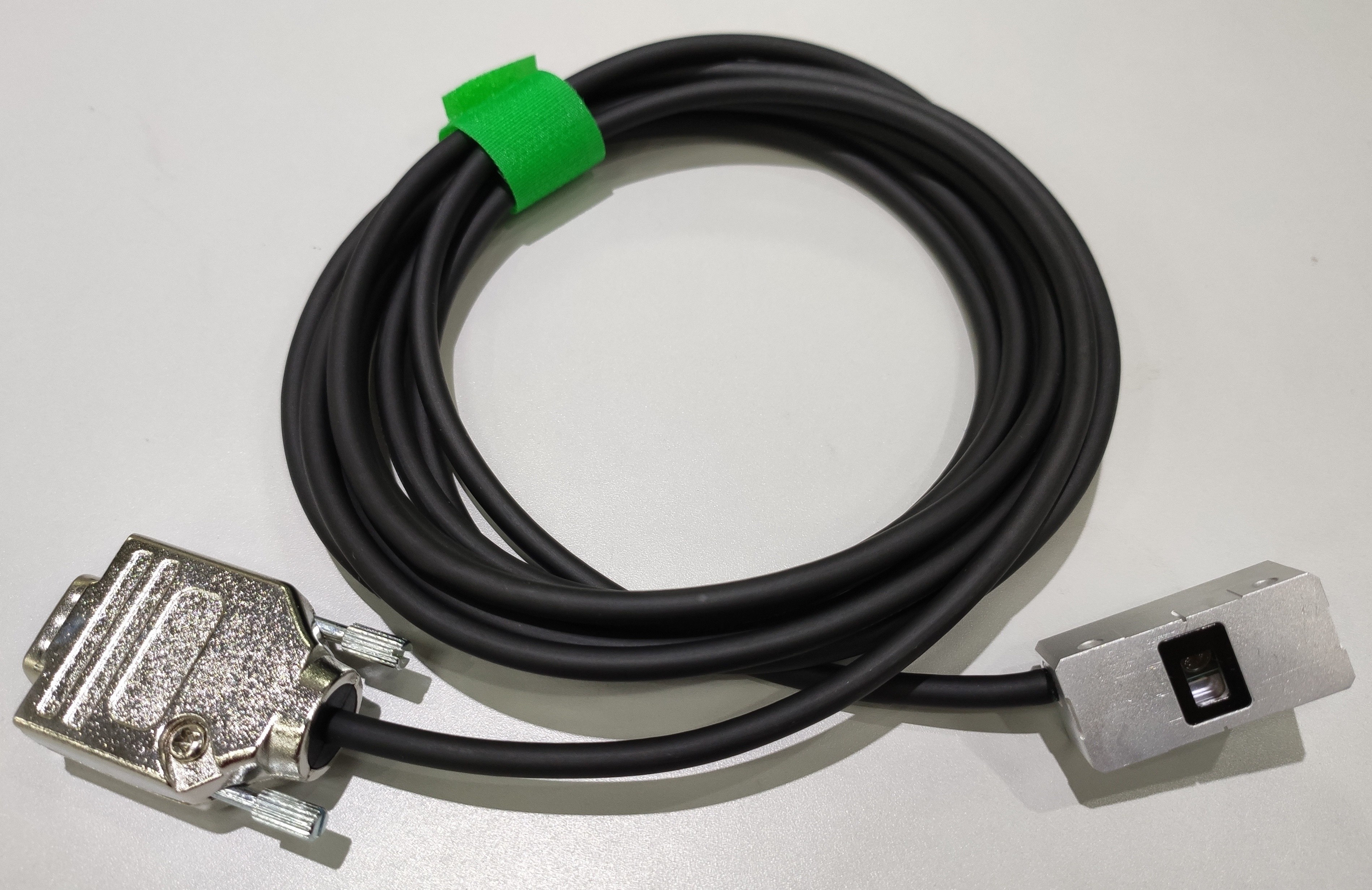
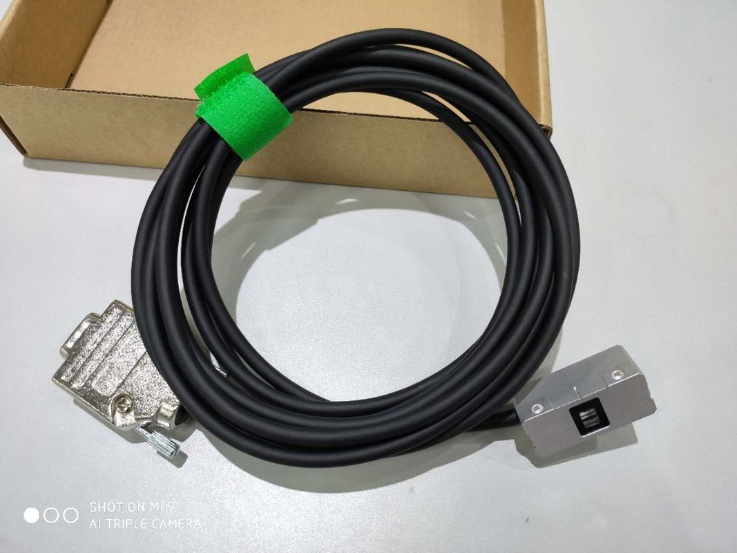
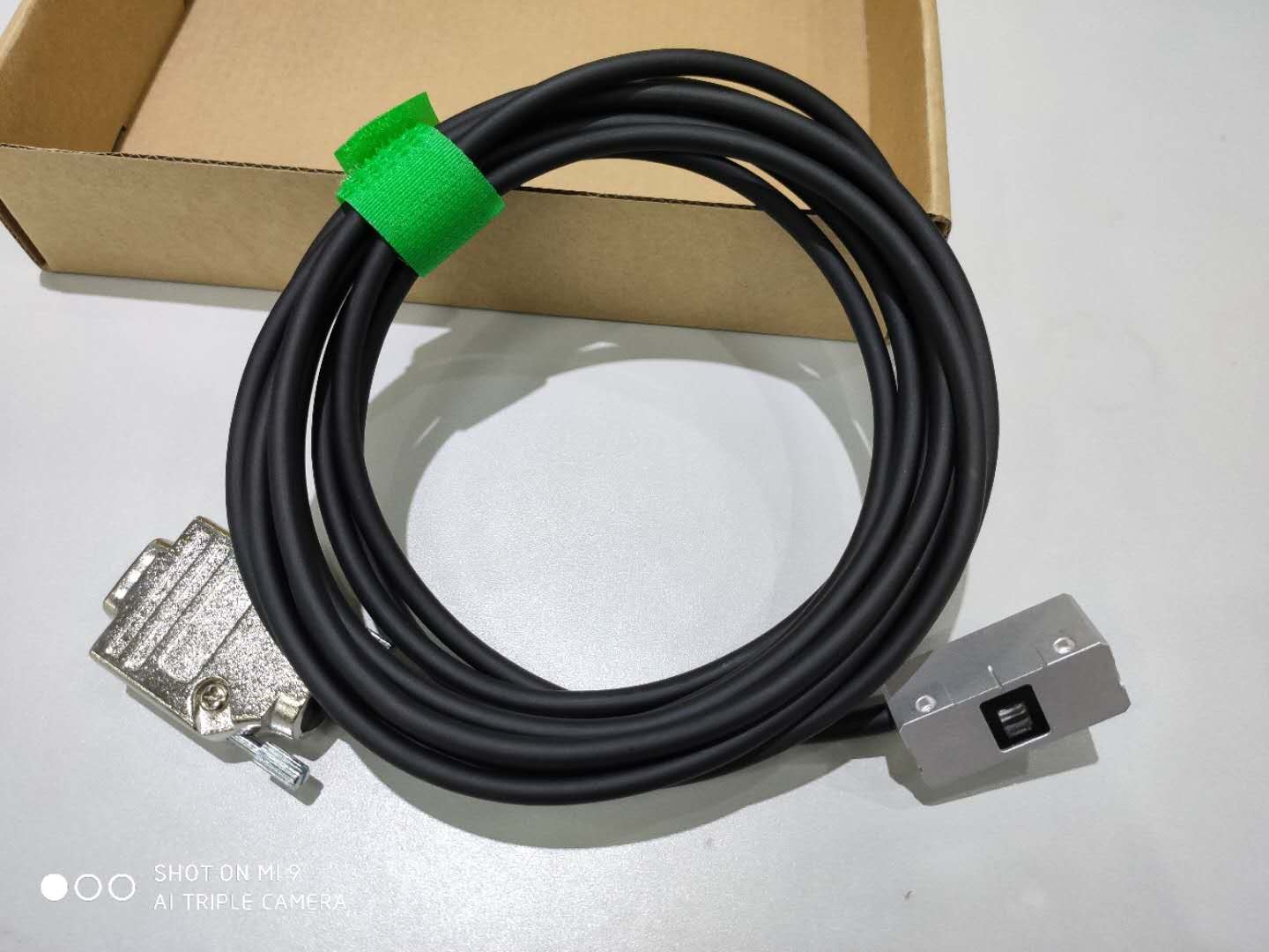
High Precision Grating Ruler Reading Head Achieve Effective Resolution Of 20 nm

Basic Information
Place of Origin: Dongguan
Brand Name: UNIMETRO
Model Number: RU2
Minimum Order Quantity: 1
Price: Discussible
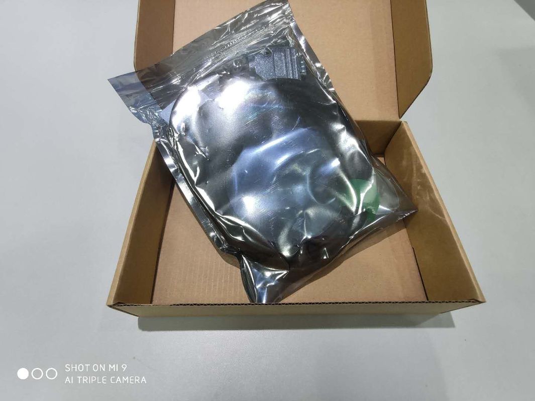
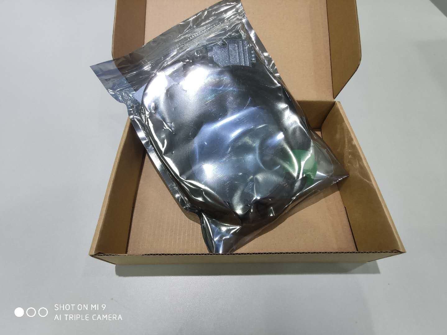
Packaging Details: box
Detail Information
Size: L36mm*W16.4mm*H14.3mm Pitch: 20um
Weight: Reading Head:15g,Cable:35g/m Signal: Differential TTL Or SinCos 1Vpp
Accuracy: +-5um Resolution: Differential TTL 5um,1um,0.5um,0.2um,100nm,50nm,20nm
Electron Subdivision Error: <40nm Maximum Speed: 12m/s(It Is Related To The Resolution And The Minimum Clock Frequency Of The Counter)
Maximum Acceleration: 35G Refer To The Unidirectional Repeating Precision At The Origin: 1LSB
High Light:

linear digital scale

,

optical linear encoder


Product Description

High Precision Grating ruler reading head achieve effective resolution of 20 nm


Product Description

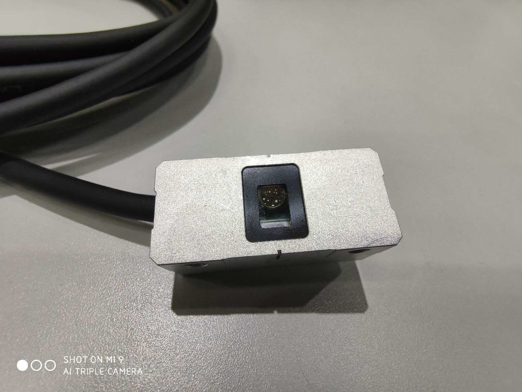
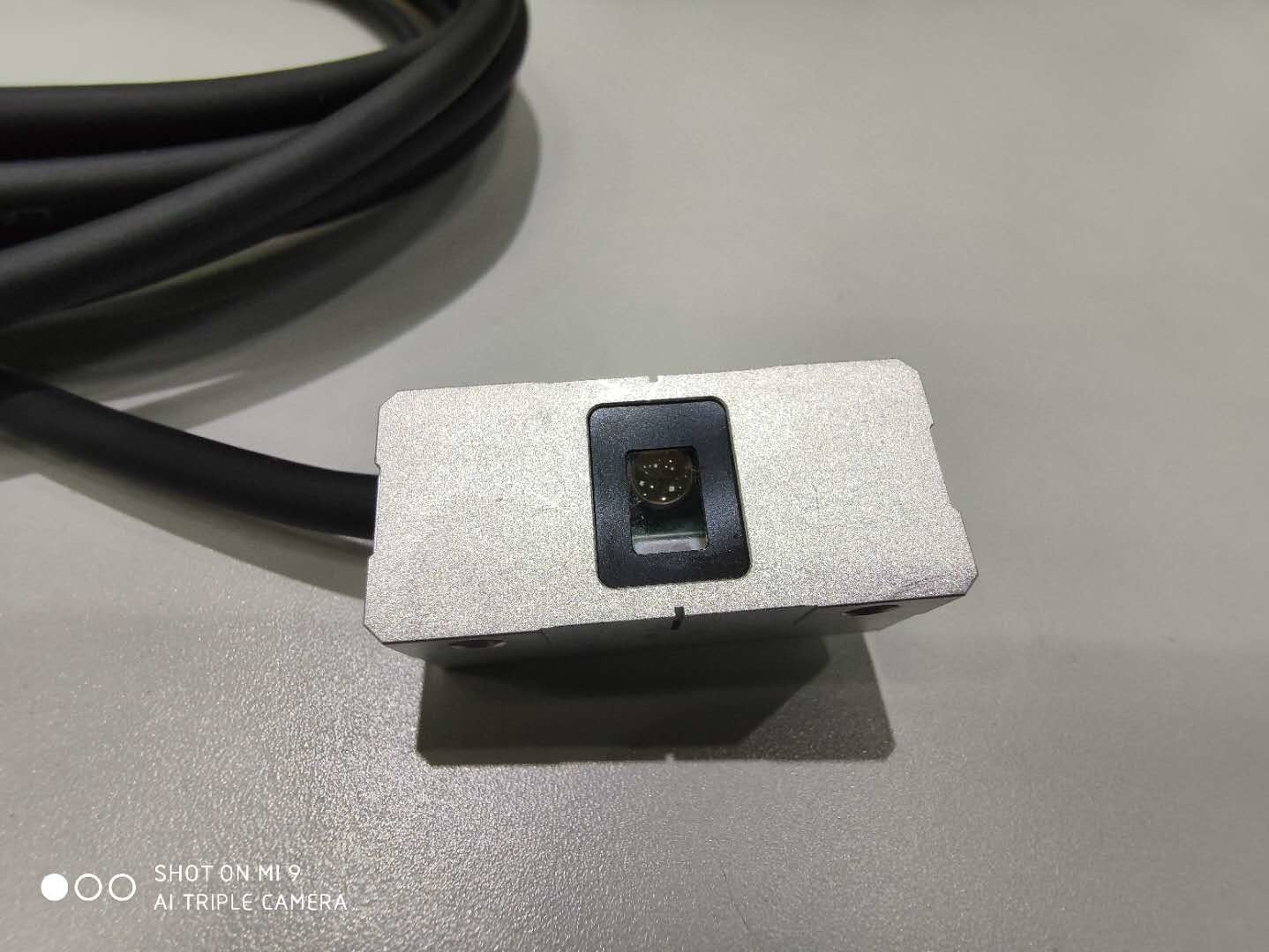
RU2 Series Grating ruler reading head

● RU2 grating ruler reading head is designed to provide feedback for high precision linear measurement. It adopts UNIMETRO' s most advanced single field scanning technology, advanced automatic gain and automatic deviation correction technology. It can read 20 MHI grating ruler with high precision and anti-pollution performance. It is suitable for high performance and high reliability applications requiring closed-loop and speed control, such as high precision machine tools and automatic deviation correction technology, High-speed automation equipment, etc.


High Precision Grating Ruler Reading Head Achieve Effective Resolution Of 20 nm 0


Reference Data

High Precision Single Field Scanning Series Reader

● RU2 reading head adopts UNIMETRO 's most advanced large area single field scanning technology, automatic gain control technology and automatic deviation correction technology, which can effectively reduce the impact of pollution. The built-in real-speed ADC subdivision of reading head can provide greater bandwidth, and more effectively reduce subdivision noise and subdivision error.It can achieve an effective resolution of 20 nm under the condition of low position noise and smooth speed control, with built-in REF reference origin and limit output, and provides a standard differential TTL digital incremental interface. The multi-color LED is integrated on the reading head, which can indicate signal strength and facilitate installation.


Environmental requirements
working temperature

-10℃ ~ +70℃

Working humidity

RH<95% (Non condensation)

Seal up

IP40

Storage temperature

-20℃ ~ +85℃

Storage humidity

RH<95% (Non condensation)


Main Features


◆ Maximum resolution 50 nm.
◆ Strong anti-pollution ability: Large area single field scanning technology, more than 100 grid lines scanning at the same time, effectively reduce the impact of other pollutants such as dust.
◆ High bandwidth, low subdivision error: built-in high-speed ADC and filter circuit, provide higher bandwidth, higher resolution, higher dynamic response, lower subdivision error.
◆ Automatic benefit control, automatic deviation correction: advanced automatic gain control, automatic deviation correction circuit and algorithm, to provide more stable signal output. Installation is also more convenient.
◆ Multicolor indicator indicates signal strength and installation status.

◆ SinCos 1Vpp, Differential TTL Signal Interface.

◆ Built-in REF origin and limit signal.


Dimension

L:36mm * W16.4mm * H14.3

Weight

Reading Head:15g Cable:35g/m

Power

5V±10% 150mA

Output signal

Differential TTL or SinCos 1Vpp, origin, limit, reading head ready

Connector

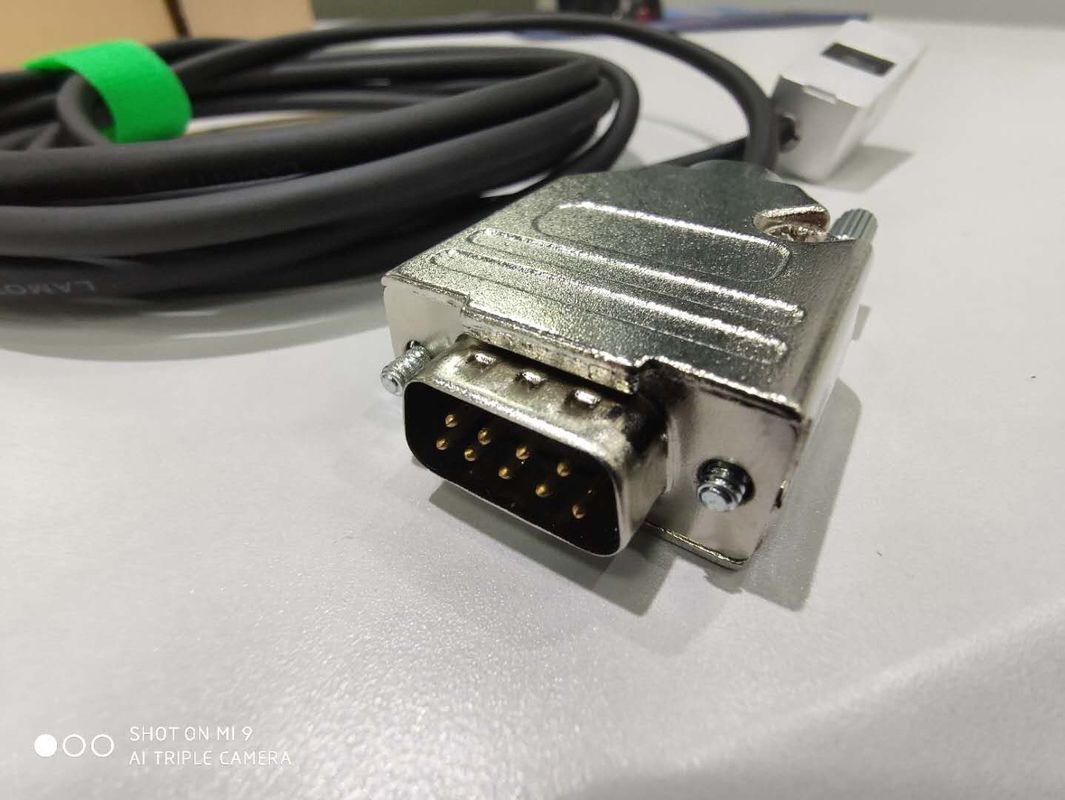
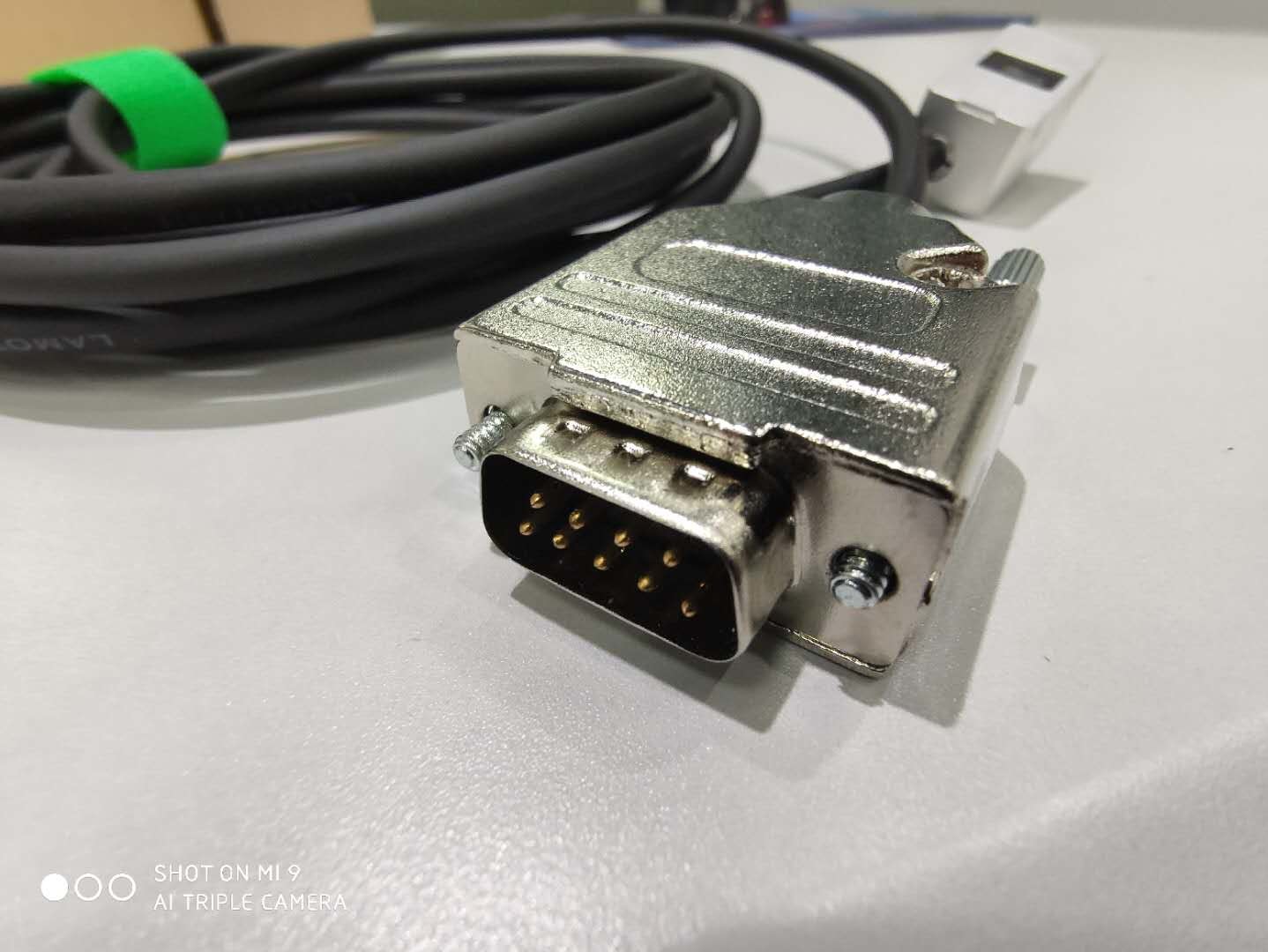
D-sub 15 Pin Male

Accuracy grade

±5 um(RUS Grating ruler)

Resolution

Differential TTL 5um,1um,0.5um,0.2um,100nm,50nm,20nm (SinCos 1Vpp)20um

Electronic subdivision error

<40nm

Maximum speed

12m/s(Relating to resolution and minimum clock frequency of counter)

Maximum acceleration

35G

Reference origin

Magnetic switch at bottom of reading head

Limit switch

Magnetic switch at bottom of reading head

One-way Repetition Accuracy of Reference Origin

1LSB


Scanning Technology


RU2 reading head adopts LAMOTION advanced large area single field scanning technology. The scattered light emitted by the light source passes through the lens and adjusts to parallel beam. After filtering the surplus beam through the window on the grating, it illuminates on the grating ruler and reflects by the grating ruler to form bright and dark fringes. The grating on the window illuminates on the single field scanning sensor.


High Pollution Resistance of Single Field Scanning


Through LAIVIOTION Dalian Banyan optical test, when using RUS stainless steel grid ruler, the RU2 reading head is polluted by dust, ink and scratches similar to the figure above, the measurement accuracy is only affected by tens of nanometers, and the Lissajou figure of the signal is only affected by a little, there will be no DC deviation and unequal distortion of the amplitude. It will not cause the reading head to be unable to work.

The single-field scanning of RU2 reading head only outputs Sin+, Sin-, Cos+, Cos-signals on one sensor. Unlike four-field scanning, it requires four sensors to output signals. When the grid ruler is contaminated, the amplitude of the signal changes at the same time, which will not cause Lissajou pattern distortion.


Automatic Gain Control Technology                                                                              

The RU2 reading head uses the most advanced automatic gain control technology of LAMOTION Dalian Banyan Optics. When the distance between the reading head and the grating ruler changes (mostly when the reading head is adjusted and installed), or when the speed of the reading head changes, the amplitude of the signal will change. The automatic gain control technology of the RU2 reading head can keep the amplitude of these signals stable all the time and ensure the output accuracy.


Detailed Images.

 
Signal electrical parameters
Differential TTL

Signal location

2 differential signals A and B

Reference origin signal

1differential signals Z

Pulse width 90°
Signal level

RS-422(TIA/EIA-422-B)

Output high level ≥ 2.4V When the output current is 20 mA
Output low level ≤ 0.4V When the output current is 20 mA
Allowable load

Output current ≤ 30 mA

Impedance 120ohm Between each pair of differential signals
SinCos 1Vpp

Signal location

Sin signal and Cos signal

Reference origin signal

1differential signals REF

Pulse width -18°~ -108°
Signal level

Signal level M 0.6V~1.2V Typical value 1Vpp

Symmetry deviation | P-N | /2M ≤ 0.065
Phase angle | φ1+φ2 | /2 90°±1°Electron angle
Allowable load

Output current ≤ 10 mA

Impedance 120ohm Between each pair of differential signals
Limit

Signal type

Drain open circuit output

Allowable load

Input level 3.3V~24V

Input current ≤20mA
Reader ready

Signal type

Drain open circuit output

Allowable load

Input level 3.3V~24V

Input current ≤20mA


PS:In order to ensure the phase of the origin signal, it may be necessary to adjust the origin magnet.


The Relation between Speed and Resolution and Frequency


Output resolution


1um

0.5um

0.2um

0.1um

50um


Counter Minimum clock frequency

10M

12M

12M

8M

4M

2M

Maximum speed

5M

12m/s

10m/s

4m/s

2m/s

1m/s

2.5M

10m/s

5m/s

2m/s

1m/s

0.5m/s

1M

4m/s

2m/s

0.8m/s

0.4m/s

0.2


Signal Connection


Reading Head Interface Line Sequence
Pin number

Function

Pin number

Function

PIN 1

Differential TTL A+ (Digital output) SinCos 1Vpp Sin+ (Analog output)

PIN 9

Differential TTL A- (Digital output) SinCos 1Vpp Sin- (Analog output)

PIN 2

Differential TTL A+ (Digital output) SinCos 1Vpp Sin+ (Analog output)

PIN 10

Differential TTL B- (Digital output) SinCos 1Vpp Sin- (Analog output)

PIN 3

Differential TTL Z+ (Digital output) SinCos 1Vpp Ref+ (Analog output)

PIN 11

Differential TTL Z- (Digital output) SinCos 1Vpp Ref- (Analog output))

PIN 4

Empty

PIN 12

Empty

PIN 5

Reader ready

PIN 13

Empty

PIN 6

Limit

PIN 14

+5V

PIN 7

+5V

PIN 15

0V

PIN 8

0V,Inner shielding (need to be connected to 0V with PIN15 to enhance anti-jamming performance)


Signal Meaning


The meaning of reader ready and limit signal can be judged concretely by referring to the system indicator.


Reading Head Interface Line Sequence
Pin number

Function

Pin number

Function

PIN 1

Differential TTL A+ (Digital output) SinCos 1Vpp Sin+ (Analog output)

PIN 9

Differential TTL A- (Digital output) SinCos 1Vpp Sin- (Analog output)

PIN 2

Differential TTL A+ (Digital output) SinCos 1Vpp Sin+ (Analog output)

PIN 10

Differential TTL B- (Digital output) SinCos 1Vpp Sin- (Analog output)

PIN 3

Differential TTL Z+ (Digital output) SinCos 1Vpp Ref+ (Analog output)

PIN 11

Differential TTL Z- (Digital output) SinCos 1Vpp Ref- (Analog output))

PIN 4

Empty

PIN 12

Empty

PIN 5

Reader ready

PIN 13

Empty

PIN 6

Limit

PIN 14

+5V

PIN 7

+5V

PIN 15

0V

PIN 8

0V,Inner shielding (need to be connected to 0V with PIN15 to enhance anti-jamming performance)


System Indicator

The RU2 reading head has built-in multi-color indicator light, which can indicate the current signal, origin and limit status, and can assist the installation and adjustment of the reading head.


Reader ready, limit signal state meaning
Signal Condition

Reader ready

Limit

Drain open

Signal line disconnection

Signal line disconnection

Low Intensity of Reading Head Signal

Detection Limit

Reading head overspeed


Abnormal power supply of reading head


Drain closure

Reading head works normally

Reading head works normally


Other Functions of Reading Head Indicator
Red lights on for 0.5 seconds

Origin position detected

Red light flashes twice

Origin phase error, need to adjust the phase The speed of origin detection is too fast.


Company Information

Visual Measurement Machine

Our Client&Agent

Visual Measurement Machine
FAQ
Visual Measurement Machine  Q1: Are you a factory or trading company ?
Visual Measurement Machine  A1: We are a factory and giving you the quickest reply in 24 hours.
Visual Measurement Machine  Q2: What's your company mainly in?
Visual Measurement Machine  A2: We are mainly produce Vision measuring machine,Coordinate measuring machine ,CMM&VMM fixturesetc.
Visual Measurement Machine  Q3: How to Choose the Appropriate Specification?
Visual Measurement Machine  A3: As long as you tell us variety and size of product to be measured, our professional team would advise you of measuring instrument of suitable specifications.
Visual Measurement Machine  Q4: Do you accept customized service?
Visual Measurement Machine  A4: Be sure! We can provide not only typical machines, but also the machines customized to customer's needs.
Visual Measurement Machine  Q5: What is your warranty period?
Visual Measurement Machine  A5: Our product warranty period is 1 year. Our product quality is very stable, and we have
improved  a lot on some breakable parts. You can rest assured of our product quality.

Contact Details
Henry Wong

Phone Number : 0086 137 0232 7661

WhatsApp : +8613702327661