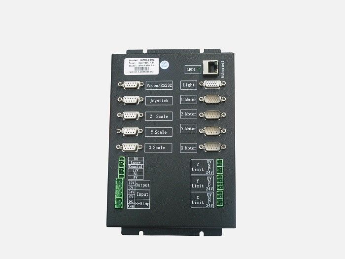
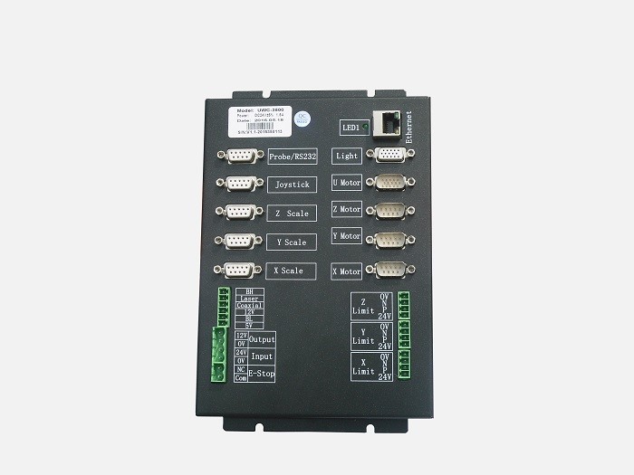
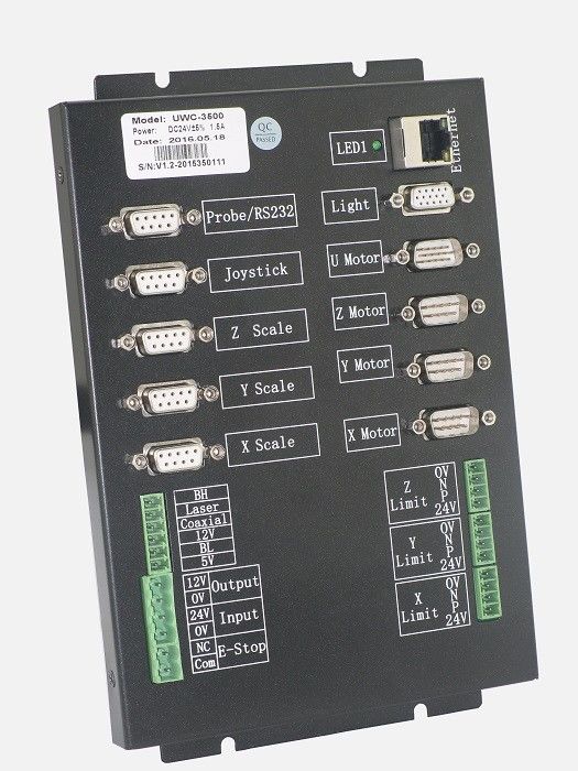
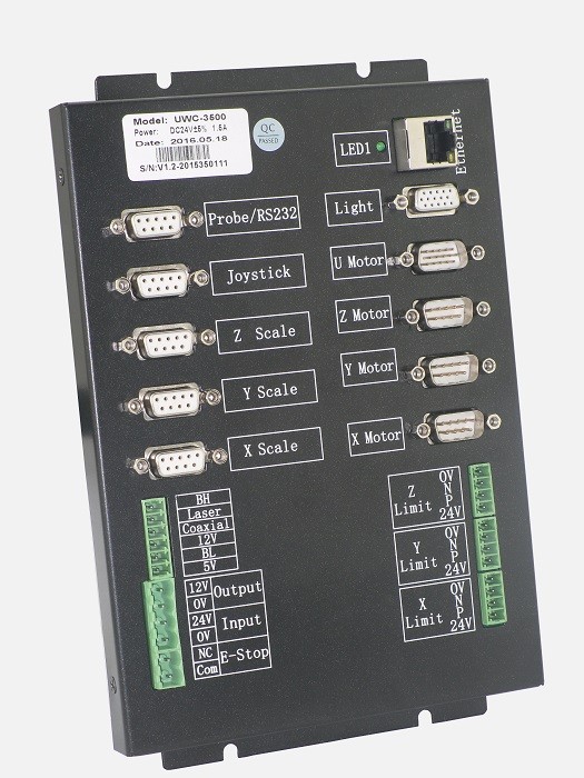
General 4 Axis Vision Measurement Machine Controller Smart Package
Introduction
UWC 3500 is a general 4 axis full close-loop controller, used in vision measurement machine and composite vision measurement machine, or automation measuring systems. With the linear scale or motor encoder close-loop position feedback, the UWC3500 is able to achieve high accuracy.
Features:
1. Advanced upper and lower machine structure, high performance CPU+FPGA
2. Communication: Ethernet interface, the running time for a single API function is lower than 0.45ms.
3. Direction+Pulse controlling mode, able to control to step motors, AC servo, linear servo or DDM, etc.
4. Full close-loop motion control, high accuracy locating which is fast, accurate, and stable. Advanced close-loop control algorithm and very few PID parameters, ensure easy turning for the users.
5. S type speed curve planing, the S section ratio in the deceleration process can be set.
6. Locating strategy:
Pulse+direction open-loop control.
Linear scale/encoder position feedback close-loop control, PID+VFF improved algorithm, eliminating the zero shifting problem.
7. Motion mode:
Point to point, JOG mode, homing mode which is easy to use and flexible, 2 axis or 3 axis linear interpolation, horizontal arc interpolation, touch probe, and joystick mode.
8. Security policy:
Auto adjusting function of the machine turning, automatically setting the limit logic and direction, the motors parameters and linear feedback direction, ensure to eliminate the feedback movement error.
When the axis move close to the limit there is an advance deceleration, and before homing there is forced restriction of the moving speed.
Software limit supported.
9. The API function is using the encapsulation facing the object, which offers easy programming. Most of the parameters are set by the debug software.
10. High integration, high performance, stable and easy production and maintenance.
11. The UWC-3500 is using SMT production technology, ensures stability and reliability.
12. With high flexibility the UWC3500 fit for the non-standard equipment and also customize of the function is available.
13. The UWC3500 is supporting the online firmware updating function, users do not have to remove the controller from the machine, easy to update and expand the function, shorten the developing and turning cycle of the equipment.
14. External UWC348 IO module, max for 26 in 26 out.
15. Position comparing matching function, which can be matched precisely, also users can set the range of matching trigger, the triggering output can be connected to the camera or laser sensor.
16. Operational stroboflash light source control function and CCD position matching trigger function.
17. Powerful debugging software included, easy operation, easy for users to turn the machine.
Parameters
| Item |
Min.
|
Typical
|
Max.
|
Unit
|
| API operation time |
0.425
|
0.43
|
0.45
|
ms
|
| Input power voltage |
22.5
|
24
|
26
|
VDC
|
| 12V auxiliary power voltage output |
11.76
|
12.05
|
12.24
|
VDC
|
| 12V auxiliary power current output |
0
|
2.0
|
2.5
|
A
|
| 5V power voltage output |
5.1
|
5.2
|
5.25
|
VDC
|
| 5V power current output |
0
|
1.8
|
2.0
|
A
|
| X/Y/Z Motor interface 24V loading capability |
0
|
3.0
|
4.0
|
A
|
| Direction pulse frequency |
-
|
-
|
6.5
|
MHz
|
| Frequency resolution |
0.006
|
-
|
-
|
Hz
|
| Linear scale counting range |
- 2147483648
|
-
|
2147483647
|
CNTs
|
| Direction pulse counting range |
- 2147483648
|
-
|
2147483647
|
CNTs
|
| Speed adjusting level |
-
|
-
|
1,000,000,000
|
32bit DDS
|
| Linear scale resolution supported |
-0.01
|
-
|
10000
|
um
|
| Linear scale signal output frequency |
-
|
-
|
6.5
|
MHz
|
| Controller general input/output |
-
|
-
|
-
|
Terminal
|
| High speed RS232 communication interface |
-
|
2
|
-
|
Terminal
|
| External IN input / output (Using one RS232 communication interface) |
-
|
24/24
|
-
|
Terminal
|
| Step driving current output |
0.07
|
-
|
1.15
|
A(RMS)
|
| Step driving subdivision |
16
|
16
|
16
|
|
Specification
| NO. |
Specification
|
UWC3500
|
| 1 |
Mpower supply
|
DC24V@2A input,output DC12V@2A(supply CCD power)
|
| 2 |
Measuring software compatibility
|
Full compatible to V1.4
|
| 3 |
Dimension
|
255 * 118 * 53(mm)
|
| 4 |
Communication
|
Isolated USB or ethernet(optional)
|
| 5 |
close-loop control policy
|
PID+VFF+ dead band
|
| 6 |
Servo refresh frequency
|
2.5KHz
|
| 7 |
Anti-mechanical shock, speed optimize
|
SMART mode
|
|
| 8 |
Axis of linear transducer counting
|
3
|
|
| 9 |
Basic control axis
|
4
|
|
| 10 |
Axis expending
|
Able to add 3 axis pulse+direction
|
|
| 11 |
XYZ axis controlling mode
|
Pulse + direction RS422
|
|
| 12 |
XYZ axis supported motors type (with external motor driver)
|
Step/AC servo/linear servo/DC servo with encoder feedback
|
|
| 13 |
U axis control mode A
|
RS232 connect to the Pomeas auto zoom lens
|
|
| 14 |
U axis control mode B
|
2 phases step driver is embedded, which support the auto zoom lens with step motors, single/duo limits are supported.
|
|
| 15 |
Speed curve planning
|
Ladder/S type
|
|
| 16 |
Interpolation
|
Multi axis linear interpolation, 2 axis arc interpolation, 3 axis interpolation
|
| 17 |
Max. Pulse frequency
|
5MHz
|
|
| 18 |
Pulse frequency resolution
|
0.001Hz
|
|
| 19 |
Speed adjusting level
|
1,000,000,000
|
|
| 20 |
Analog voltage control
|
-
|
|
| 21 |
Linear transducer counting frequency
|
6MHz/(A or B Phase)
|
|
| 22 |
Linear transducer signal definition
|
R or S for optional (R:12345, S:26789)
|
|
| 23 |
Probe measuring hardware
|
Touch probe interface circuit
|
|
| 24 |
Probe error processing circuit
|
Available, auto repair of the probe nonhoming
|
|
| 25 |
Compatible probe
|
Renishaw/Tesa all series trigger touch probe
|
|
| 26 |
Probe processing module
|
Probe high speed latch, joystick control touch point auto pause and auto retreat, auto detecting point mode
|
|
| 27 |
Joystick signal collecting card embedded
|
12 bit resolution, 0-5V analog voltage input, 3 press button and 3 LED, emergency stop switch included, speed adjusting knob including (mutually exclusive used with 3# button)
|
|
| 28 |
Embedded illumination control card
|
8 section surface light + bottom light + co-axial light, 0-200 level software adjusting
|
|
| 29 |
Lighting grade setting function
|
16 level hardware adjusting in the parameter setting base on the brightness requirement
|
|
| 30 |
contour light control capability / LED bank control
|
Max. 420mA, fit for most of the large travel machine
|
|
| 31 |
External complicated type lighting interface
|
Able to connect to 5 rings 8 section single color programmable light, or 5 rings 8 section 4 color programmable light, elevated / rotatable light
|
|
| 32 |
General I/O interface
|
8 section isolated input, 5 output (ULN2803 compatible)
|
|
| 33 |
System clock
|
Year-month-day-hour-minute-second, can not be modified
|
|
| 34 |
Firmware upgrade
|
Customer upgrade on site, offering fast solution and technical updating.
|
|
| 35 |
Probe connector
|
9 pin D-DUB connector, easier for wiring and more stable
|
|
| 36 |
Joystick connector
|
OTP6, OTP7, HC3(Multi-keys joystick)
|
|
| 37 |
Joystick data processing
|
The controller internally process the joystick data and motion control, mutual with the other motion control mode, joystick probe touching with auto stop and auto retreat
|
|
| 38 |
External emergency stop
|
The emergency stop button controls the motor power supply
|
|
| 39 |
Speed curve planning
|
Ladder / S type
|
|
| 40 |
Software limit switch
|
Available
|
|
| 41 |
Software deceleration point
|
Available
|
|
| 42 |
Appointed distance braking
|
Available
|
|
| 43 |
Supported debugging software
|
V4.0 version or above (Auto detecting and setting parameter)
|
|

 Your message must be between 20-3,000 characters!
 Please check your E-mail!
  Your message must be between 20-3,000 characters!
 Please check your E-mail!

