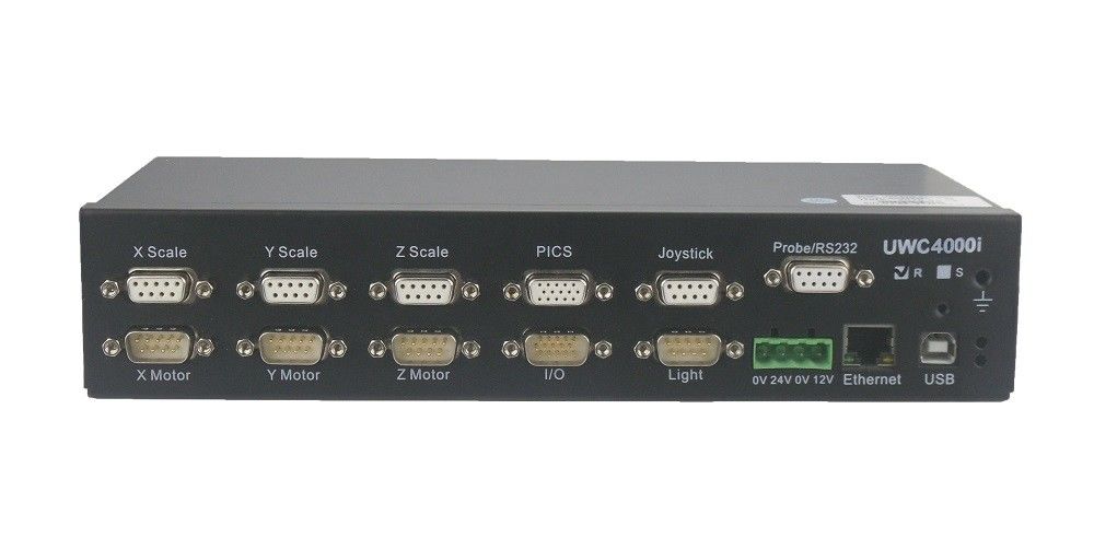
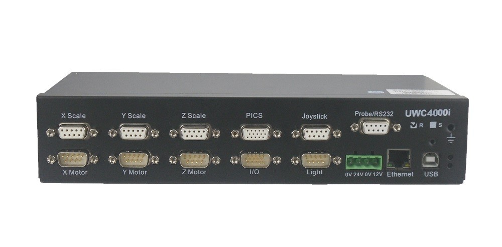
2D 3D Automatic Vision Measurement Machine Motion and Illumination Controller
Introduction
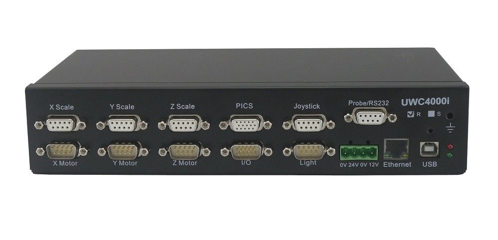
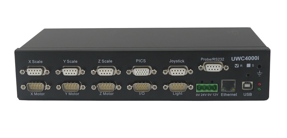
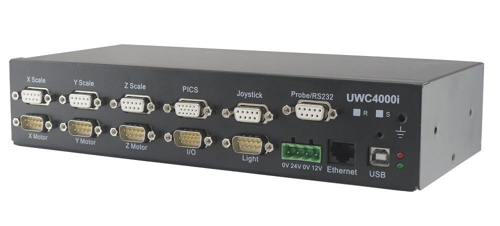
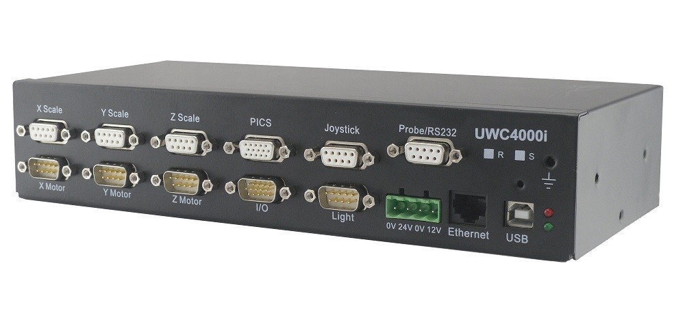
UWC-4000i is an independent controller using the second generation advanced UWC technology. It is a specialist controller for CNC video measuring machine and coordinates measuring machine. UWC-4000i is embedded with 4 axis motion control, 3 axis linear transducer counting, 10 terminal illumination control, joystick data collecting processing card and probe function, offering an SIC (System In Case) solution for the high-end CNC VMM and general CNC CMM.
Working Principle

Features
1. Full close-loop control in the hardware phase (PID close-loop control protocol with Velocity Feed Forward and dead-band control, the refresh frequency of the servo is 2.5KHz), real-time adjusting of the motor rpm based on the linear transducer position feedback, to ensure the locating process completed when the motion planning ends (within the appointed locating accuracy). A one-time fast locating is promised with all kind of transmission structure, and more efficient when rigidity is higher. This optimize time consuming and gain much high efficiency.
2. Multiple transmission structure are supported, such as linear drive, ball screw, synchronous belt, multi-polar belt, wire rope and steel belt, etc. The speed curve is planned by higher-order function, which ensures the stability. (Transmission structure with high backlash such as gearing is not supported)
3. 3 axis motors rpm is using direction + Pulse adjusting mode, eliminating the null drift of the analog voltage control. The machine is in full static status when the software is capturing the image, reducing the abbe error caused by single end driving of the transmission device, ensures the measuring accuracy.
4. 10 terminal 3200 levels adjustable constant current control connects to the LED directly, 8 terminal are used for surface light, 1 for the contour light and 1 for the co-axial light. It is the best replacement for the normal illumination controller which is large and unstable. If more section of surface light is needed please make reference to the illumination manual.
5. UWC-4000i is embedded with direct joystick interface, which eliminates the data lagging situation of the traditional USB joystick, and improve the operation performance of the programming, single piece measuring and the probe measuring process. Probe automatic searching, auto feedback, error protecting function eliminates the crashing risk, and reduce difficulty of the PC software programming.
6. There is no PCB inside the compatible joystick of the UWC4000i but only few wiring is required. So users can design the appearance and style. We will offer the main schematic and the parameters of the components. The emergency switch and speed adjusting knob are embedded.
7. The UWC-4000i uses only a single USB cable to connect the PC, and no need for the PCI slot. This makes the wiring much more easy and smart, and increase the stability.
8. MOF function(Measure on the fly), capturing the image during the stage moving process, which much reduce the time consuming of the measuring process, and increase efficiency.
9. The axis control is using direction + pulse output motion control mode, RS422 level output, able to connect to varies signal of DC servo / AC servo / intelligent motors (SMART motors, Coolmuscle motors from UWC). It is suitable for the motors with encoder feedback or step motors.
10. All the API function support the multi-lines programming, the executing time for a single API function is 3.2-3.8ms.
11. The motion control programming considers the 2D / 3D measuring features and the user operating, offering user friendly programming and operation interface.
12. UWC4000i-R and UWC4000i-S are optional for 3 axis linear transducer counting. The connectors are directly compatible to all the common brands of linear transducers, supporting single-ended and difference square wave signal.
Application
The 4000i controller applied on a CNC automatic vision measurement machine.


Specification
| NO. |
Specification
|
UWC4000i-V1.5
|
| 1 |
Measuring software compatibility
|
Full compatible to V1.4
|
| 2 |
power supply
|
DC24V@2A input,output DC12V@2A(supply CCD power)
|
| 3 |
Dimension
|
255 * 118 * 53(mm)
|
| 4 |
Communication
|
Isolated USB or ethernet(optional)
|
| 5 |
close-loop control policy
|
PID+VFF+ dead band
|
| 6 |
Servo refresh frequency
|
2.5KHz
|
| 7 |
Anti-mechanical shock, speed optimize
|
SMART mode
|
| 8 |
Axis of linear transducer counting
|
3
|
| 9 |
Basic control axis
|
4
|
| 10 |
Axis expending
|
Able to add 3 axis pulse+direction
|
| 11 |
XYZ axis controlling mode
|
Pulse + direction RS422
|
| 12 |
XYZ axis supported motors type (with external motor driver)
|
Step/AC servo/linear servo/DC servo with encoder feedback
|
| 13 |
U axis control mode A
|
RS232 connect to the Pomeas auto zoom lens
|
| 14 |
U axis control mode B
|
2 phases step driver is embedded, which support the auto zoom lens with step motors, single/duo limits are supported.
|
| 15 |
Speed curve planning
|
Ladder/S type
|
| 16 |
Interpolation
|
Multi axis linear interpolation, 2 axis arc interpolation, 3 axis interpolation
|
| 17 |
Max. Pulse frequency
|
5MHz
|
| 18 |
Pulse frequency resolution
|
0.001Hz
|
| 19 |
Speed adjusting level
|
1,000,000,000
|
| 20 |
Analog voltage control
|
-
|
| 21 |
Linear transducer counting frequency
|
6MHz/(A or B Phase)
|
| 22 |
Linear transducer signal definition
|
R or S for optional (R:12345, S:26789)
|
| 23 |
Probe measuring hardware
|
Touch probe interface circuit
|
| 24 |
Probe error processing circuit
|
Available, auto repair of the probe nonhoming
|
| 25 |
Compatible probe
|
Renishaw/Tesa all series trigger touch probe
|
| 26 |
Probe processing module
|
Probe high speed latch, joystick control touch point auto pause and auto retreat, auto detecting point mode
|
| 27 |
Joystick signal collecting card embedded
|
12 bit resolution, 0-5V analog voltage input, 3 press button and 3 LED, emergency stop switch included, speed adjusting knob including (mutually exclusive used with 3# button)
|
| 28 |
Embedded illumination control card
|
8 section surface light + bottom light + co-axial light, 0-200 level software adjusting
|
| 29 |
Lighting grade setting function
|
16 level hardware adjusting in the parameter setting base on the brightness requirement
|
| 30 |
contour light control capability / LED bank control
|
Max. 420mA, fit for most of the large travel machine
|
| 31 |
External complicated type lighting interface
|
Able to connect to 5 rings 8 section single color programmable light, or 5 rings 8 section 4 color programmable light, elevated / rotatable light
|
| 32 |
General I/O interface
|
8 section isolated input, 5 output (ULN2803 compatible)
|
| 33 |
System clock
|
Year-month-day-hour-minute-second, can not be modified
|
| 34 |
Firmware upgrade
|
Customer upgrade on site, offering fast solution and technical updating.
|
| 35 |
Probe connector
|
9 pin D-DUB connector, easier for wiring and more stable
|
| 36 |
Joystick connector
|
OTP6, OTP7, HC3(Multi-keys joystick)
|
| 37 |
Joystick data processing
|
The controller internally process the joystick data and motion control, mutual with the other motion control mode, joystick probe touching with auto stop and auto retreat
|
| 38 |
External emergency stop
|
The emergency stop button controls the motor power supply
|
| 39 |
Speed curve planning
|
Ladder / S type
|
| 40 |
Software limit switch
|
Available
|
| 41 |
Software deceleration point
|
Available
|
| 42 |
Appointed distance braking
|
Available
|
| 43 |
Supported debugging software
|
V4.0 version or above (Auto detecting and setting parameter)
|

 Your message must be between 20-3,000 characters!
 Please check your E-mail!
  Your message must be between 20-3,000 characters!
 Please check your E-mail!

