Manual Vision Measurement Machine Controller Probe function Lighting Controll
Introduction
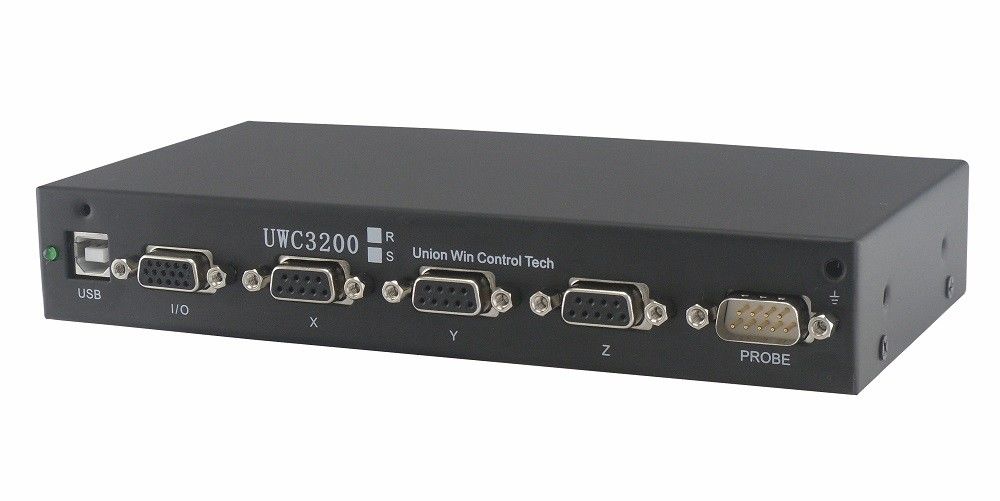
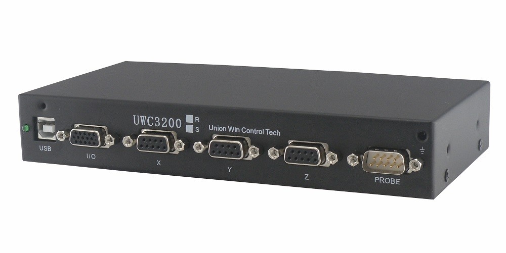
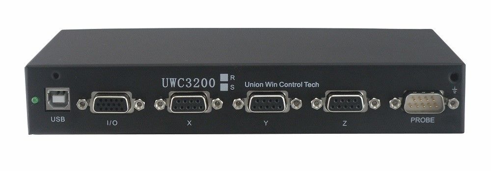
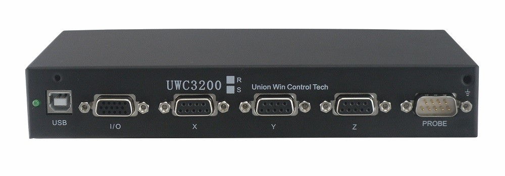
UWC3200 is including the encoder / linear transducer counting, touch probe latch, illumination control, Z axis motion control, using a USB cable connecting to the PC, supporting the 32 bits and 64 bits operation system. UWC 3200 offers a One Case solution for manual vision measurement machine, it is smarter, lower cost, better performance and more stable comparing to the traditional manual VMM controlling system.
Working Principle

Features
1. 3 axis linear scale counting, able to connect to the single-ended (TTL) or difference (RS422) square wave signal linear scale of any brand.
2. Programmable surface lighting function, able to connect to 4 sections, 8 sections (100mA/section) or one section (300mA) surface light.
3. Programmable contour light, able to connect to a single LED light with 1.6-3.5V working voltage, or a multiple LEDs light with 6-11V working voltage.
4. Co-axial light / laser indicator function, able to connect to varies co-axial light of 3.3-5V working voltage.
5. The software adjusting range of the brightness of the illumination is 0-200; the surface light hardware adjusting level is 1-16, 1-20 for the contour light and co-axial light. When the software adjusting is in a certain level, for example 200, change the hardware adjusting level will increase or reduce the real current running.
6. Z axis CNC motion control function, pulse direction signal output, which is including jog, point to point, homing, MPG motion controlling mode. The point to point motion mode is an advantage to the Z axis fast focusing.
7. Touch probe interface, the hardware will latch the 3 axis linear scales data in real time. When the Z axis is with CNC control, the Z axis will auto retreat after the touch probe touching point.
8. MPG following function, use the MPG to control the Z axis traveling speed and distance; MPG speed range: 0.1um/s-10mm/s. When using the MPG control, the maximum surface light section is 4.
9. Using the optoelectronic isolated USB data communication, to ensure the anti-jamming performance and communication stability. Eliminates the losing signal problem. Supporting the Windows XP, Win 7, 32 bits and 64 bits operation system.
10. The API is designed based on the vision measurement machine and coordinates measuring machine application. Only several API should be needed to complete all the operation. The UWC 3200 professional debugging software will complete the complicated parameters setting and motion adjusting operation. The API supports multiple lines programming,
11. Working power: 12VDC, the rated working current is 0.5A without connecting to the illumination. It is able to use the PC power supply for the power source.
Application
UWC3200 applied on a manual vision measurement machine, achieve programmable illumination and Z axis motorized, auto focus available.


Parameters
| Model |
|
|
|
Power supply
|
Without surface light control
|
12VDC+5%@0.5A(max)
|
|
With surface light control
|
12VDC+5%@1.5A(max)
|
|
Linear scale counting
|
Counting axis
|
3 axis
|
|
Interface definition
|
Gigabite ethernet (1000Mblt/s)
|
|
Rational-WH type:Rational 9BD connector
|
|
Power output capability
|
5.0-5.15V@0-130mA/axis, if the linear scale power is more than 130mA, do not connect the scale VCC to the UWC3200, but external 5V power supply is required.
|
|
Signal type (compatible)
|
RS422, signal cable length less than 20M
|
|
TTL, signal cable length less than 10M
|
|
Input frequency
|
RS422:<6.5MHz
|
|
TTL:<4MHz
|
|
Resolution @ moving speed: 1um@6.5M/S,0.1um@650mm/S
|
|
Resolution support: 10mm—— 0.05um<4MHz
|
|
Motion control
|
Controlling axis
|
1 axis(Z axis)
|
|
Close-loop control policy
|
PID+VFF+ dead band
|
|
Servo refresh frequency
|
2KHz
|
|
Speed planning
|
S type speed curve
|
|
Anti mechanical shock, speed optimization
|
SMART mode
|
|
Touch probe processing
|
The controller is not processing, but only sets a sign position, the software will do the stop/retreat.
|
|
Close-loop control axis
|
Z
|
|
Close-loop control axis
|
Z
|
|
Output
|
PULSE+DIR
|
|
Output signal frequency
|
0—400KHz
|
|
Output signal electrical parameters
|
When the resolution >=1um, +-2 grating counting pulse equivalent
|
|
Locating accuracy
|
Imax=50mA
Triode electrode open circuit output
|
|
Compatible transmission structure type
|
Ball screw, leaner drive
synchronous belt / iron belt
Ladder ball screw
|
|
Lighting control
|
Controlling mode
|
Common positive pole constant current drive
|
|
Surface light output capability
|
One section: 300mA@0-11V
4 sections: 100mA@0-11V /Channel, user made ring light
8 sections: 100mA@0-11V /Channel, compatible with UWC4003B
|
|
Contour light output capability
|
100mA@0-4V or 6-11V
|
|
Co-axial light output capability
|
100mA@0-4V or 6-11V
|
|
Software brightness adjusting range
|
200 levels
|
|
Hardware brightness adjusting range
|
Surface light: 1-16, bottom light and co-axial lighe: 1-20
|
|
Working condition
|
Storage environment
|
-20~80℃, no condensation, no oil, acceleration <2G
|
|
Working environment
|
0-40℃, no condensation, no oil, acceleration <1G <2G
|
|
Mechanical parameters
|
Closed painted iron box
|
|
Fixing screws: M4 * 4
|
|
Dimension: 255*120*53mm
|

 Your message must be between 20-3,000 characters!
 Please check your E-mail!
  Your message must be between 20-3,000 characters!
 Please check your E-mail!


